
The Western Maryland Western Lines in N Scale is currently undergoing a significant reconstruction.
My train room is in the attic of my home, so I wanted to avoid having to lug too much stuff up and down the steps. Fortunately I have an old outbuilding garage that serves as a splendid workshop. Thanks to some timely phone calls when the old county vo-tech school was torn down, I picked up one of those great old shop tables. You know the kind, with four giant vises on the corners, a 2" thick rock maple top and lockers underneath. I also picked up some of the shop tools for a song.
As such, I am able to carry out most of the dusty, noisy and smelly aspects of layout construction outside the house. Then, when it's ready, I lug the semi-completed module upstairs to the train room.
As of January, 2011 I'm well underway rebuilding the layout into the plan shown here. So far, work has proceeded to complete the installation of the Thomas Sub tracks all the way to Elkins, and the Connellsville Sub has been extended all the way to a point just below the Cumberland Station. The main line through Cumberland is now under construction, with scenery work being installed toward the rear of the platform. Also, the foundations of the new west staging yard have been installed, and the next big push will be to extend the tracks across the window. Once that connection is made, the Connellsville line will descend to West Staging via a two and half turn double tracked helix, and the main line will enter the new Ridgeley Yard. The last piece of the puzzle will be to tie the main line back into North Junction to access East Staging, then operating sessions can resume. I'm hoping this will happen by the end of the summer of 2011.
![]()
Here is the revised track plan. The only elements that survive from the previous configuration are the Luke Paper mill section and North Junction. Everything else is being substantially reconfigured.
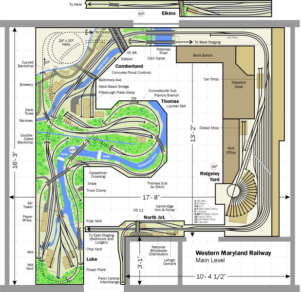
Drawing by David K. Smith.
This configuration will enable an operating scheme that closely follows the flow of traffic on the Western Maryland: Coal and timber running on the twisting and climbing Thomas Sub to Elkins, and fast freight bridge traffic running down the Connellsville Sub, through Maryland Jct. and Ridgeley Yard, and east to Baltimore or Shippensburg. The key will be balloon staging tracks at the east and west end of the modeled portion.
A major change that will add operational interest is the extension of the Thomas Sub to Elkins by way of a small helix. My original plan included Elkins, but it was crowded up against the larger yard at Ridgeley, which would have been cluttered visually, and difficult to operate due to the level of activity concentrated in a narrow area of the room. By elevating Elkins to a higher lever, it improves the illusion of distance, and visually and operationally separates the coal traffic from the main yard. This portion of the expansion is completed.
New Plan Lower Level Staging (West and East Staging)
![]()
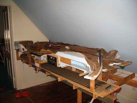
I'm using several different types of benchwork depending on the conditions of the location. The frame is designed to be somewhat modular. I plan to stay in my home for the foreseeable future, but in today's economy, one never knows. The larger sections along the left and right sides are all L-girder tables with 1x3 open joists. I'm using wall brackets and cross bracing to limit the number legs I need, since I want to keep the area below the layout open for storage.
Under Luke I have a semi-hidden staging yard that is accessible from the aisle. The left hand yard lead loops up and over itself to reach the drop-leaf bridge at North Jct. This carries trains from the 5th dimension (Baltimore and Lurgan) onto the modeled portion of the railroad, headed west to Hagerstown Yard. This yard is now reconfigured as a 4-track balloon staging yard, meaning that trains go into staging, turn around a loop, then return to the layout from the same direction. This vastly improves operations, as cars that have waybills that send them off to the east, can now return from the east in a more logical pattern.
A similar four track balloon has been added to the west end, representing the west end of the Connellsville sub. This end of staging is the destination of trains bound for the P&LE connection at Dickerson Run, the N&W at Rook, and the PRR and B&O at Bowest, as well as Laurel Valley trains from Rockwood Jct. and is accessed by a helix below the yard at Ridgeley.
The scenic base under the Luke paper mill is built up using 1x1 framing that carries a 1/4" plywood deck. 3/4" foam is then laminated to that to make the land forms.
The peninsula uses a simple L girder frame, with 1x risers and 1/2" plywood cut in "cookie cutter" fashion for sub roadbed. The narrow parts of the layout are to be built as shelves, using steel brackets to attach them to the walls. The Elkins Yard is built on a hollow core door to maintain a low profile for this elevated section. These are connected permanently to the large sections, although there are three removable sections for access to the closet, the window, and the main entrance to the room. These locations are noted on the diagram.
Aside from keeping the mess and fumes out in the garage, building the layout segments in the shop has another very real benefit. When I installed the wiring for the track, turnout motors and scenic lighting, I could tip the layout up on end and work standing up with the wiring right in front of me. No hot solder falling in my hair! This helped me keep the wiring much neater, and the junctions more secure.
The scenery base is extruded blue foam, attached with Liquid Nails, sculpted with a Stanley Pocket SureForm, and coated with a skim coat of Sculptamold that is tinted with earthtone acrylic paints. On top of this I use a variety of materials and colors to create the look I want depending on the scene. I use Woodland Scenics and Scenic Express ground foam products, various brands of sand and stone products, an many natural materials. See the scenery section of the Projects page for more details.
I chose Atlas Code 55 flex and sectional track for the visible parts of the layout, as well as their turnouts. Like many, I had heard about the difficulties that some people were having with older equipment with large flanges, such as "legacy" locomotives (those made before 1980) and MicroTrains and old Kadee rolling stock. Since I had changed my modeling theme from an Early Conrail concept to the Western Maryland circa 1970, I had replaced most of my fleet with newer models. I did have to update many of my remaining cars, about 100 at the time, but that was done incrementally so the hit on Mr. Wallet wasn't so bad.
Since it's introduction a couple of years ago, I've been thoroughly impressed with the appearance of the track. Now that I have a fair amount installed, I'm equally impressed with its operational characteristics. The ability to wire the frog on the turnouts virtually eliminates stalling, and they work exceptionally well with Tortoise slow motion machines, which are the standard on my mains. Even fully ballasted the turnouts work well.
The track is installed on Midwest Cork n scale roadbed, which is adhered directly to the foam base with Liquid Nails. I use a thin screed of yellow Elmer's Construction Glue to install the track. It forms a bond quickly, and holds well even with the moisture that's added during ballasting. I solder most rail joints, leaving a few for expansion and contraction.
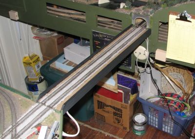
In the staging yard, I used Atlas code 80 standard flex track and Peco turnouts. I made this decision because I had a lot of it leftover from previous layouts, and my goal was to save some money. The code 80 to 50 transitions are located at the ends of the leads where the track returns to view.
For control, I chose the MRC Prodigy Advance Digital Command and Control system, which has proven to be extremely user friendly for an otherwise "technology-challenged" modeler. I understand the system has some limitations compared to other more complex systems, but so far they have not affected my enjoyment of using it. I will be adding a second power district when the Ridgeley Yard is reinstalled, and am considering upgrading to wireless operation. For reversing units, turnout controls and so forth, I've used components from various manufacturers, including North Coast Engineering, Digitrax, and TCS.
As noted, the main-line turnouts will be all operated by Tortoise slow motion switch machines made by Circuitron. Ultimately, I'll wire these to decoders so they can be operated remotely by the hand held throttles from MRC. For now they are wired to control panels situated near the location of the switch, and can be easily operated by the engineer as his train approaches. During a formal operating session, I can assign a "tower operator" to the major points, and at some point down the road, I may build a remote Dispatcher's Office in the next room. All turnouts in switching areas, and most on the Thomas Sub, are manually operated, using small Double Pole-Double Throw slide switches. These are inexpensive, and a lot less obtrusive than Caboose Industries ground throws.
I use separate power supplies for track, turnouts, scenic lighting, and other accessories.
Don't underestimate the importance of finishing your layout room before you start your building benchwork. When I bought the house, which was built circa 1905, the attic room was a shambles. The only electricity was a single bulb fixture in the ceiling with a pull string. No outlets anywhere. The plaster was crumbling, and there was no insulation in the roof.
It took about 3 years of DIY and elbow grease, but I finally got it done, with nice paneling and sheetrock. I ran all new circuits, including two banks track lighting that operate on separate dimmers. I also included a ceiling fan, and a new circuit for a window air conditioner (no central in the house...yet) When I was done, it almost seemed a shame to fill the room up with a layout...
Naah!
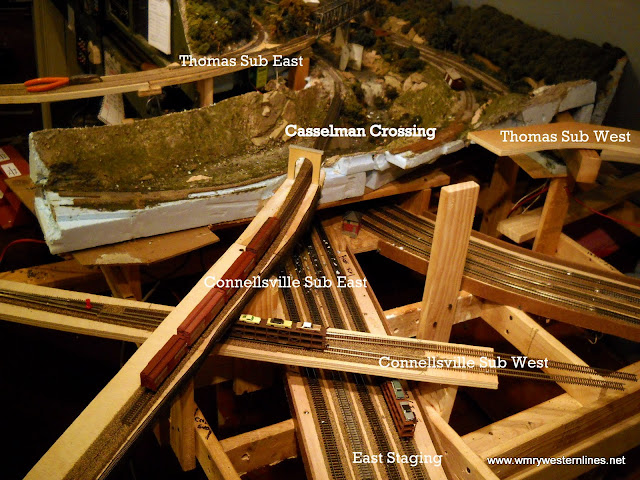
The following image diagrams how the various routes come together where the peninsula meets the Cumberland side of the layout. It's quite a challenge engineering everything to both fit, and work smoothly. While I'll have access to all of these runs below decks, my goal is to have it operate as trouble free as possible.
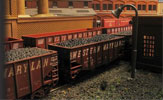
The next image shows the recently installed Ridgeley Yard area viewed from the east end above the roundhouse.

Anyway, now I have a nice comfortable finished room in which enjoy my hobby, and invite others over to run trains or just hang around and railfan the layout.
As the rest of the layout gets built, I'll provide additional updates. If you have any questions, you can contact me here: lee.wildcard.graphics@gmail.com.
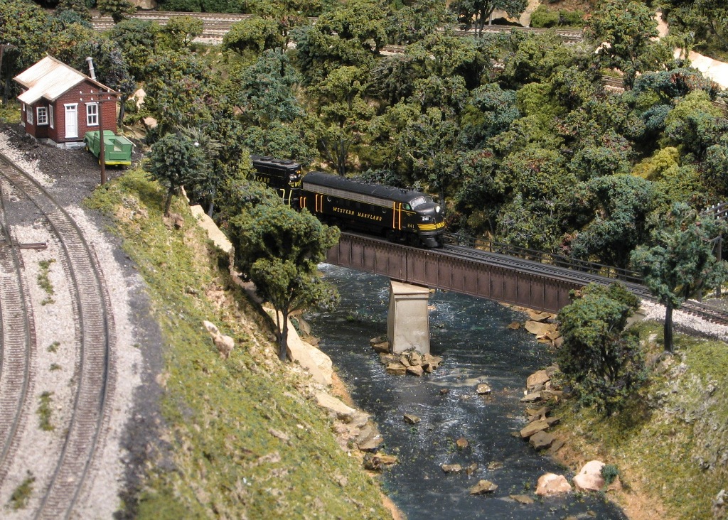
The reconstruction will change the appearance of this scene, which was featured in the November/December 2010 N Scale Magazine. The bridge will stay, but the lines to the left (on the embankment) and the right, have been altered substantially. You can follow updates on the progress of the reconstruction by visiting my blog.
I've put together a slide show that takes you through the early parts of constructing the Western Maryland Western Lines layout. I've used fairly conventional construction methods.

Elkins Yard. This is constructed on a 12" wide hollow core door, cut to length and mounted on three steel shelf brackets. Beyond this platform to the left is a narrow shelf that carries the line from the yard throat at Elkins to the top of the helix behind Cumberland. Part of the shelf is removable to accommodate the window, which has to be opened periodically to install the air conditioner during the summer. Click HERE for more photos of the construction of Elkins.
The shelf section at North Junction, and the drop leaf that crosses the aisle. Modular jacks make disconnecting the bridge a snap.
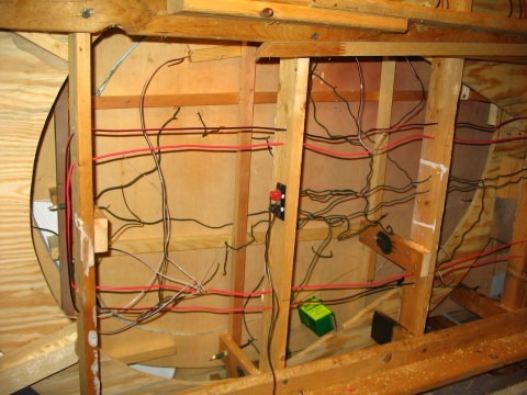
Building the layout in sections allows you to do your wiring and minor adjustments to turnout motors while standing up in the workshop instead of on your back in the layout room.

Atlas Code 55 track before ballasting
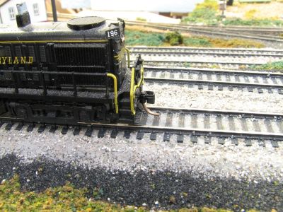
...and after. Lately I'm using a 50/50 blend of Woodland Scenics light grey fine ballast and a light to medium grey colored sand product available from a craft store. The WS chunks add some texture without overwhelming, while the sand fills in and has a good close to scale appearance.
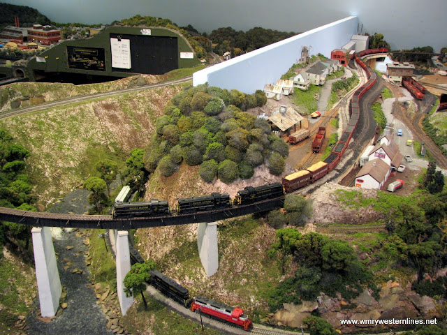
From The temporary loops were removed in May of 2010, and the peninsula has been expanded to create this scene, where the Thomas Sub crosses the river valley on the high bridge, while the Connellsville line snakes along the riverbank below. More photos of the construction of this area can be found HERE.

In this scene, the Thomas Sub crosses Wills Creek west of Cumberland near the back of the layout.

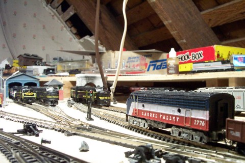
I started building my Laurel Valley Railway layout before I started renovating the room in ernest, as you can see by the crumbling plaster and gerry-rigged extension cords. It took about 3 years working more or less by myself, but it was well worth the time and effort to rewire and finish the room.